Hello again,
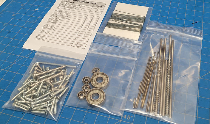
I'm starting this post as a way of sharing my progress on my new Moon Phase Clock build. For starters, I wanted to showoff the hardware kit that came in the mail today. At first, I was contemplating putting this kit of non-printed parts together myself. But I'm so glad I chose to buy Steve's kit instead. So worth the cost, as it would have taken me forever to put together a quality hardware set like this. Shipping was quick, thanks Steve ;-) , and the packaging was perfect. The kit comes with everything, including the correct size drill bits for the arbors. All of the arbors are nicely cut to length and the ends are de-burred. The minute hand arbor is already ground with the needed flat on it. The bearings are already cleaned and de-greased. All of the required springs are included (and shipped on the arbors for protection; clever). The screw package includes flat, pan and socket head fasteners, along with the hex key for the socket heads. And finally, the required fishing line, which is nice, heavy braided (no stretch) line. Nice work on the hardware kit Steve! Only bummer is there was no candy included!

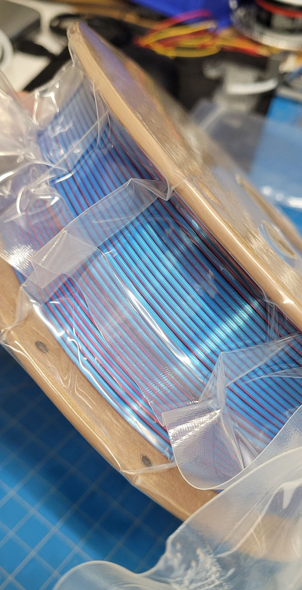
I also received a new spool of Sovol Silk Magic Tri-Color PLA in Blue-Yellow-Fuchsia to try out for the gears. I will report back on how this material performs (and looks). Part of my goal with this choice is to somewhat replicate the look of Steve's gears using the MatterHackers Quantum Blue-Rasberry PLA, which I think is beautiful. But that stuff is expensive, and not sold by Amazon (Prime).

I hope anyone seeing this post will follow along as I attempt to build this beautiful work of a 3D printable clock. I am totally open to any and all comments and suggestions as I go. When I first saw this clock on Youtube, I was so blown away. I just had to have one. Time to start loading some STL files into my Prusa Slicer. More progress to follow.
Cheers!
Despite my clock running & keeping good time, it has stayed in my room being tweaked up. It needs over 8 pound to drive it, I think I have found the problem area. The other concern I had, the pallet did not line up with the escapement to my satisfaction. What I have discovered will possibly sort out my weight problems as well ( I hope).
Checking on the gear pallet, I find that my Z axis is significantly off, resulting in about 1/4 tooth engagement with the escapement gear. (I gather Z axis a common problem with the Ender 3 v3 SE), this has resulted in all Z axis structures are off, I guess its putting some twist in the whole frame.
Until I brace the Z Axis, I still have a functional clock, I love watching it.
I will reprint a few parts once I get the bracing done, and rehouse it in a permanent place.
Just putting this out there Steve, in case others have similar problems with their Enders!
The Moon Phase Clock build was a hit on the 3D Printing Reddit Subgroup, and pretty much went viral within hours of posting. In 48 hours it got 46,000 Views, 835 Likes, 100% Upvote Rate, 75 Comments, and 110 Shares. It went on to win me 2 rare Reddit awards, a Piccaso and a Rising Star Award, lol. There were a lot of questions asked and I answered every one of them.
Hi Salty, that’s nifty!
I want to show you all a secret feature of my clock build. The face ornamentation is removable, and just snaps in between the inner dial face surface and the bottom edges of the globes. The outer edge of the inlay design was offset inward by 0.5 mm all around, and the layer lines act like tiny locks, holding it in place. Works great actually. The inlays are 3 layers thick for the base, and 3 layers thick for the embellishments. My plan is to draw up different looking ones for different seasons and events that I can quickly swap out for the occasion.
Thanks Salty, our apt is pretty much all black & white, so to keep the peace….you know that dance, huh?
I’m pleased to say that my Moon Clock is up & running, at this stage I am running 4 pound weight on a single strand until get my pulley & weight shell set up. Photos to follow once I get it out of its temporary home.
This project has exceeded my long desire to make a clock, I am living in an apartment with no “Man Shed”, so anything messy is frowned on by Her Indoors. I did have a few problems on the way, (all solved by reading the instructions), one was I did not press the bearing home in the “back upper b”, making me wonder why the pallet was not engaging the escapement.
The Non printed parts kit was a real asset for me, worth every cent.
I have to admit that my clean up of printed parts was a tad sloppy, I didn’t need to file any gear profiles, trim the elephants feet, only remove a few whiskers on some parts…..but I did pay attention to cleaning the bores out, making sure the pendulum swung in excess of 5 minutes.
What surprised me was, despite not having any experience with 3d printing prior to late Nov 24, I managed to print the parts for the clock, minimal elephant foot, a few hairs, and a clock that has managed to run inside 2 minutes fast in 24 hours. Adjustments made' results in 24 hours…..
100% happy, recommend this build to anyone wanting a functional clock!
Watching with interest for the updated clack you mentioned recently.
Thanks Steve!
Hello fellow 3D Printed Clock Enthusiasts,
Below are two links to videos of my clock running. The first is meant for Steve, and is quick to show the escapement and pendulum only. The second is an also short Overview. Turn on the Sound icon for sound. Thanks for following the build.
Cheers!
Video: Escapement and Pendulum Only
Video: Short Overview
Well salty, that looks magnificent! You have personalized that clock!
Mine is still in pieces, I have finished adjusting the frame dowels, done some assembly.
The instructions are a great help to the budding builder!
Hope ti gave a hanging ceremony in the next few days…
Edit: It wouldn't upload the video referred to in this right-up. I will try posting it separately.
Hello All,
The clock is finished and I am happy to report that it is running like a charm. At first I needed at least 7.5 lbs to run it, but after some additional tweaking of the escapement wheel, which is absolute key in my opinion, I can get it to run on slightly less than 6 lbs. Currently, I have settled on 7lbs 4 oz, which is the 3 inch short shell, filled completely with lead shot, and it has been running super steady all day. Steve, if you watch the video, how does the escapement performance look? I think I’m getting a nice, steady, relatively strong lock, with a steady pendulum amplitude of 2.4° using the 7lbs4oz.
Here are the numbers from my tests:
Weight Amplitude
7lb 4oz 2.4°
7lb 0oz 2.2°
6lb 0oz 1.8°
If anyone wants to know more about a few of the gory details that I went through in an effort to fully optimize this clock, to my potential at least, let me know. If you notice a piece of black plastic glued to the back of the escapement wheel, that is part of it.
This has been one of the funnest, most rewarding projects I have worked on lately. I strongly recommend trying out one of Steve's designs. You will get to push your 3D printer to it's full potential. And you will learn a lot about clocks, which I have found fascinating. I might be hooked!
Hello fellow clock makers,
I hope you all had an awesome holiday. Happy New Year to all. I was so anxious to get back to my clock project while on holiday visits. This project is addictive. I've made lots of progress since, and what follows are lots of pictures to document what I have done. Hopefully, this will be useful for someone later. But more importantly, hoping that if Steve sees anything goofy, he will let me know 😎
All of the printing went well overall. I had a few print failures that needed re-starts, but that was all on me. And I needed to re-print two gears that didn't come out as nice as I wanted due to poor bed adhesion. The parts are all phenomenally well designed for 3D printing and are user friendly. Nice work Steve!
All of the parts have been post-processed by weeding, de-burring, arbor and bushing drilling, and some light sanding at PLA on PLA areas. Everything was test fitted in the frame, and I took the time to do the gear to gear friction tests, two gears at a time, moving up the train. Taking the time to really feel out each element is valuable. I went back several times for some more cleaning to get it just right. In fact, there was some friction between my in my Gear 1 and it's arbor that I fiddled with a bit. T 1.5mm x 3" arbor is long and needs to be really straight. The bore in Gear 1 is quite long and neither the supplied drill bit, nor any of the millions that I have, were long enough to go all the way through. Because the bore is printed vertically, any slight misalignment between the top and bottoms of the bore can be tricky to clear out since the bit doesn't pass all the way through to get a true alignment. However, the kit had an extra, 3" long, 1.5mm arbor that I chucked up in my drill and ran that through the gear a number of times to burnish it into alignment. That worked great and it literally took every bit of remaining friction out of Gear 1.
I did use a Teflon based lubricant on all of the arbors, and also a light film where gears and spacers touch the frame, or the gears themselves. All of the two-at-a-time, gear-on-gear tests went really well, with what I perceived as just about the minimal friction I think I can achieve with my equipment and skill.
I also took the time to do the pendulum by itself test. That also went well and the pendulum swung for more than 20 minutes from a 2° amplitude offset for a start. It seemed like it would have gone forever. At the 20 minute mark, it was swinging only about 1/8" on a side, but still moving, and I called it good. My pendulum is using the ball bearings that came in Steve's parts kit, so obviously, those are well chosen and prepped. I just dropped them in and did not do any cleaning of my own as it looked like Steve had already applied Teflon lubricant after his cleaning op.
Here is what I have so far.
And here it is with all the gears installed. Feels really good turning the gear train by hand. And feels really good getting to this point.
I temporarily mounted the clock low on the wall for working, and performed the pendulum swing duration test. It easily swung for more then 20 minutes.
OK, I'm really tired now. My next step is going to be to run the clock without the pallet to break it in an get a feel for how things are rotating and sounding. And see how smooth the gear train runs on it's own. I am super excited about getting to that point as this is my first clock and I'm anxious to see what that looks like; for this thing to be running like a little motor transmission.
Cheers all!
The parts pack arrived today, very pleased with it too! I have finished printing all of the parts, had a break over Chrissy & will start to assemble the clock tomorrow. After visits to Doc, Dentist! In Oz, dentists are Fang Farriers, Docs are Quacks or Vets.
Looking forward to seeing it on the wall!
Keep smiling!
Without people pushing the boundaries, would there even be advances on Gen 1 3d printers? New filaments? Keep pushing!
And have a great Chrissy!
Silky looks great! I don’t do the experiments you do in printing, I’m just happy to see them coming off the plate clean…..thank god others push development in those areas!
Hello all,
I've been steadily printing frame parts in the silky silver. Really liking the results with this filament. The gears are all finished. And I've been messing around with the 3D moon, cause I think it's so cool.
This project is fun and interesting in many ways. For one, it required me to break my record regarding the largest part I have ever printed on one of my two printers. So far, that is the frame-back-center. As can be seen in the closeup, it took up just about all of the available build plate. Heck yeah!
Playing around with the 3D moon sample cookie, I've been experimenting with producing as much contrast as possible between the dark and light areas. The pic below shows nearly the most you can get, by making the first white layer print as thin as possible. I've been doing this by using different combinations of the first layer height, and the subsequent layer height, which allows you to position the layer change M code just about anywhere you want in the model.
Cheers all!
That looks amazing Salty!
Hello All,
While I'm busy still printing clock parts, I thought I would show off some remixing I am doing of the moon gear. I am an amateur astronomer and wanted to show constellations that are familiar from my latitude, and done so in the theme of a common star chart. The top half shows Orion and Canis Major looking south, and the lower half shows Ursa Major and Virgo looking North.
I have printed a few small cutouts of the model with Orion in it to get the printing of the tiny stars and connecting constellation lines dialed in. This remix is not a job for the "filament stringing" faint at heart. You have to get nearly all stringing out or else you're left with a mess. I have it really close by modifying my slicer code to slow way down during the star field printing, with double retraction, and a small lift.
Now, back to printing clock parts. Gears are all done; starting on frame parts next.
Cheers to all!
Well, away we go, madly printing coggy things & brackety things for my Moon phase clock. Briefly, I am retired, "Age Enhanced", living in Oz (Australia). I had never considered buying a 3D printer until we went to buy one for a young relation, Wife Of Mine, said that I should buy one for myself- so I did. Printing cute tugboats & other related items don't attract me, I made a few brackets & trays to hold camera gear.
I always wanted to build a clock, and luckily I stumbled on Steve's page, and decided on the moon phase clock. For our house, I have decided to build black & white (I love B & W photography as well). The second bit of luck is Steve selling the Non Print items as I have nowhere to do that sort of work in our apartment.
I am amazed by the amount of thought that has gone into this design, plus the backup How To files, and the responses to other builders questions.
As the photo shows, I doubt I will be finished printing before Sandy Claws arrives......
The white Gear 0 may become black as time rolls by, and I intend replacing the globes on the dial will become photos of 2 treasured family members.
Merry Ho Ho Ho to to all!
Hello Steve,
On my SP14, is gear10-60-moon-3d.stl available in .step like moon-flat is? I was trying to play with some remixing of the stars, which was easy on -flat starting with the step file in CAD. But for -3D, starting with stl is practically impossible with the apps I'm using. No biggie if not. Just checking.
Thanks.
Hey Phil,
No worries on that failed gear, it's just corn and sugarcane turned into plastic somehow, lol. Good luck. Show us your prints.
Hi Salty, printed 7 gears so far, one had a Dentist’s Delight on it, so I reprinted it (after re slicing). Looks like a slicing problem, all the faults started on the plate & gradually faded out over 3/4 of the tooth.
Keep laughing…..
Hello All,
Happy to report, knock on wood, that my DIY i3 clone is back up and running. The Arduino Mega went out on it. Although I've struggled today with 3 nozzle clog events that kept me from getting a single gear out. Even after cleaning and replacing all the parts on my nozzle. I finally switched filaments and so far so good. Which is strange because I printed the first 8 gears on the clogging spool before problems started. Not sure. Still kind of a mystery. We will see if the big, giant gear8-54 (actually it's a 8-60) makes it through the night. While we wait, I thought I would create some content and show off some of my 3D printing world. The first pic is of my little DIY printer right after the Arduino Mega replacement this morning. I designed and build this based on a clone of Prusa Mk2.5, right after it hit the market. It has served me well, and cloning was very helpful to learn how these little printers work.
This second pic is my current bench top bread board of the guts that will go into the DIY printer once I get it all working. I'll then have a modern 32-bit processor, the super quite TMC2209 stepper drivers, and a color touch screen display. Which is a game changer for printer control. I have it all alive and able to control the peripherals. I just need to figure out how to compile Marlin now for the whole setup.
Going with the upgrade is not only learning about the latest hardware, but also just as important, learning how to use Visual Studio and the PlatformIO Extension to edit and compile the firmware. The upgrade adds the need to edit, compile and upload firmware to the TFT display as well. In the past, one could just use the Arduino IDE to edit, compile, and upload everything. Not so anymore. The tech has gotten sophisticated enough that a dedicated programming environment, like VSC, is almost a must. Which I have very little experience with. Luckily, it's all on YT.
The thing to understand in closing with this little rant (and something it took me a bit to wrap my head around) is that the TFT touch screen displays that you find on nearly all 3D printers today are actually small processors themselves, and can act completely as a host for the printer. They are a little mini-computer, that communicates with the printer via serial (RS232). So instead of the Arduino running the display like in the old days, the display controls the printer and vice-versa, bi-bidirectionally. It's a great way to go now that I understand the concept. The possibilities are endless now. Well, cost and physical memory aside.
Cheers all!
Hello all,
Here is an update. I made great progress the last few days, completing 8 gears, and printing one of the frame parts in light, bright silver (to mimic polished aluminum) and the clicker/ratchet parts in silky gold to see which color I like moving forward. I really like the silver. It does look close to machined aluminum.
Unfortunately, the 3D printer I was using decided to die on me today right in the middle of gear. I think the Arduino Mega 2560 motherboard met it's end. I do have a second printer, a Prusa Mk2.5S, but it has been busy printing presents for the grandchildren. May have to interrupt that job, LoL. I have a new Mega on order. And I'm also playing around with a bench top setup to see if I'm ready to upgrade my DIY printer to 32-bit and touch screen. I have the wire breadboard bench top system partly working.
Cheers to all!
Hi all, watching with interest! I too can see the value in buying the parts kit rather than chasing around looking for the right parts. It cost me $57 Aus , plus $38 freight, but still a bargain imo. Disappointing to see
it took Steve about 10 minutes to pack the order!
Looking forward to seeing other builders work, and rearing to go with mine.
I have a Ender 3 v3 SE (first printer, bought it 3 weeks ago. I have made a few racks for camera lenses, brackets to attach bits on a tripod. A clock? Here we go!
While I'm waiting for my 3rd gear to print, I thought I would share how my gear printing is going, and also some Prusa Slicer work flow tips that are helping me stay organized. I think my first few gears are coming out incredible. Mostly due to Steve's excellent design for 3D printing practices. Steve, I am impressed. Design for 3D printing was part of my job as a Mechanical Engineer, so I understand what it takes to develop great printing models.
The first image below is a screen grab of one of my gears after slicing. As recommended, I am using the Arachne perimeter generation algorithm, 5 perimeters, and a 0.2 first layer height followed by 0.15 layers. With these settings, I am getting the continuous print paths as recommended for really strong gears with minimal outer imperfections (see video in second image below). The only place I deviated was with the Seam algorithm, which I think I read Random was preferred. But I feel I am getting way better results, as shown below, with Aligned. I dislike the pimply texture that Random produces, and honestly, where those end up on mating gear surfaces I think would cause problems. With Aligned, the seams always end up on an inside corner, and always at the bottom of a gear tooth where it won't affect anything.
And finally, I'd like to share a Prusa Slicer work flow Ive been using that helps me move along faster and stay better organized with progress. The last image shows a screen grab of my current Prusa Slicer Project for the gears. The first thing I do is bring all of the STL files into the one slicer project session, and organize them in order along the top and off the build plate. Having everything in a single project lets me more easily use the same print settings for all of the gears, and helps me avoid mistakes while better tracking progress. All of the files will be listed in the right panel for easy reference. Under View, I turn on Show Labels, which provides a file name badge for each part in the graphics for easy identification. Then, I move each gear onto and off of the build plate, slice, and export. As I complete the printing of each gear, I turn off that corresponding model in the slicer's right panel listing. That serves as a check mark that that gear is done, and changes it's color in the graphics window. I can save the project, close, and pickup right where I left off in subsequent sessions.
I hope these tips are helpful to others.
Cheers!
Gear 1 is fresh off the hotbed, and it printed out flawlessly. This is using the Tri-Color type filament I purchased for the gears, and although I think it looks great, I'm actually not thrilled about the way it distributes the colors over the part. Any change in average diameter of the tool path for a given layer tends to drastically change the color. This is super evident where it changes from the large diameter gear part, to the smaller diameter arbor, where it goes from a rainbow coloring to a sudden purple. I have some Dual-Color filament on the way (like what Steve has been using) that I will try next that will likely produce more gradual color transitions. Gear 2 is printing.
Thanks for the great write-up on the parts kits. I try to keep the cost as low as possible by buying in bulk and making 10-20 kits at the same time to keep labor costs low. I actually timed how long it takes to put together each kit to put it in the cost spreadsheet. Labor is the largest category. For example, each 1.5mm arbor material cost is $0.05, but the labor to cut and debur is $0.15 per piece. I have a jig that allows me to cut 10 at a time and debur 5 at a time. The labor for the 3mm rods is $0.50 each because they need to be done individually. I will have to see if candy can be added and still fit in the flat shipping boxes. :)
The MatterHackers blue raspberry PLA is listed because it seemed like the only option when the manuals were written. Since then, there is a lot more competition. I started using Eryone from Amazon. It works just as well at about a third of the price. Here is a screen capture from the first page of an Amazon search for "dual color PLA". Another brand is even cheaper.